Occasionally we’re asked to troubleshoot failed phone calls; however, in some case we are provided very limited details on the situation or symptoms under which the failure occurred. To ensure consistent troubleshooting of these failed calls, I’ve compiled the following guidelines below that I occasionally reference to ensure I’ve covered all (or most) possible scenarios.
Internal calls not ringing to a phone:
- Verify the phone is registered to Communications Manager.
- Verify the originating phone can call other directory numbers.
- Verify the destination phone is not forwarded to voicemail, or another destination.
- Verify whether the phone can be called from a different originating phone.
- Verify the destination directory number is configured with the correct partition.
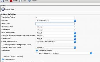
- Verify there are no translation patterns that might be changing the called number.
- Verify the Ring Duration timer on the directory number is set high enough to allow the phone to ring.
- Run the Route Plan Report to verify there are not shared extensions on multiple devices, one of which might be seizing the call or controlling call routing (busy trigger, etc)
External Inbound calls not ringing to a phone:
- Verify the phone is registered.
- Verify the PRI circuit is in service using the process outlined on page 2.
- Debug inbound calls using the process defined on page 3.
- Verify the call is received from the telco.
- Verify the incoming called number defined in the debugs matches a translation rule/pattern, dial-peer, or internal directory number.
- Verify the translation rule/pattern is not changing the inbound called number to a different destination.
- Verify the directory number partition is visible by the CSS on the gateway or translation pattern.
- Verify the internal directory number is not call forwarded to another destination.
Unable to complete outbound calls:
- Verify the user is dialing the appropriate access code (e.g. 9) in your environment for an outbound call.
- Verify the number being dialed is the correct number and length for the area being called.
- Verify the following information:
- Verify the number is valid by calling from a cell phone, or other external device.
- Verify the called number matches an existing route pattern or dial peer.
- Verify there are no translation patterns that may be changing or blocking the called number.
- Verify the PRI circuit is in service using the process outlined on page 2.
- Debug outbound calls using the process defined on page 3
- Verify the calling number is defined correctly using the External Phone Number Mask, Route Pattern/List, or translation pattern/rule. (Most carries reject calls if calling number is incorrect.
- You can use the Dialed Number Analyzer on CUCM to verify the db most of these; however, q931 debugs may also be required.
Unable to forward a phone to an external local number:
- Verify the Call Forward All calling search on the directory number is set to the appropriate CSS.
- Verify the destination number includes the access code for an outbound call.
- Verify the destination number is a valid number by calling from another phone, or a cell phone.
- Verify the calling number is defined correctly using the External Phone Number Mask, Route Pattern/List, or translation pattern/rule. (Most carries reject calls if calling number is incorrect.
Debugging Circuit Issues on the IOS Voice Gateway |
Verify the ISDN-PRI circuits are operational by checking the “ Layer 2 Status” of the circuits using the command ‘show isdn status’. Layer 2 status should show ‘State = MULTIPLE_FRAME_ESTABLISHED”.
Below is an example of a PRI circuit that is out of service.
ROUTER#sho isdn stat
Global ISDN Switchtype = primary-4ess
%Q.931 is backhauled to CCM MANAGER 0x0003 on DSL 0. Layer 3 output may not apply
ISDN Serial0/1/0:23 interface
dsl 0, interface ISDN Switchtype = primary-ni
L2 Protocol = Q.921 0x0000 L3 Protocol(s) = CCM MANAGER 0x0003
Layer 1 Status:
DEACTIVATED
Layer 2 Status:
TEI = 0, Ces = 1, SAPI = 0, State = TEI_ASSIGNED — Circuit is down
Layer 3 Status:
0 Active Layer 3 Call(s)
Active dsl 0 CCBs = 0
The Free Channel Mask: 0x00000000
Number of L2 Discards = 0, L2 Session ID = 37
Below is an example of a PRI circuit that is in service.
ISDN Serial0/1/1:23 interface
dsl 1, interface ISDN Switchtype = primary-ni
L2 Protocol = Q.921 0x0000 L3 Protocol(s) = CCM MANAGER 0x0003
Layer 1 Status:
ACTIVE
Layer 2 Status:
TEI = 0, Ces = 1, SAPI = 0, State = MULTIPLE_FRAME_ESTABLISHED — Circuit is up
Layer 3 Status:
0 Active Layer 3 Call(s)
Active dsl 1 CCBs = 0
The Free Channel Mask: 0x807FFFFF
Number of L2 Discards = 0, L2 Session ID = 17
Total Allocated ISDN CCBs = 0
If the circuit state is TEI ASSIGNED, check the status of the T1 controller. Review the lines in bold in the output of the show controller t1 x/x/x output.
ROUTER#show controller t1 0/1/0
T1 0/1/0 is up. —- Would say “T1 0/1/0 is down” if circuit was down or cable is disconnected.
Applique type is Channelized T1
Cablelength is long gain36 0db
No alarms detected. —- Would say “Remote alarm detected” if circuit was down.
alarm-trigger is not set”
Soaking time: 3, Clearance time: 10
AIS State:Clear LOS State:Clear LOF State:Clear
Version info Firmware: 20060711, FPGA: 13, spm_count = 0
Framing is ESF, Line Code is B8ZS, Clock Source is Line.
CRC Threshold is 320. Reported from firmware is 320.
Data in current interval (473 seconds elapsed):
0 Line Code Violations, 0 Path Code Violations —- Check data in the
0 Slip Secs, 0 Fr Loss Secs, 0 Line Err Secs, 0 Degraded Mins —- current interval for
0 Errored Secs, 0 Bursty Err Secs, 0 Severely Err Secs, 0 Unavail Secs —- for errors or slips
Data in Interval 1:
0 Line Code Violations, 0 Path Code Violations
0 Slip Secs, 0 Fr Loss Secs, 0 Line Err Secs, 0 Degraded Mins
0 Errored Secs, 0 Bursty Err Secs, 0 Severely Err Secs, 0 Unavail Secs
Debugging Circuit Issues on the IOS Voice Gateway (con’t) |
If the circuit state is TEI ASSIGNED, check the ISDN q921 messages to ensure transmission and receipt of q921 messages. Review the lines in bold in the output of the show controller t1 x/x/x output.
You should see a transmit (TX) and a receive (RX) packet for each circuit. If either a TX or a RX is not generated, it could indicate a hardware or cabling issue affecting the T1 module in the router, at the smartjack, or at the telco.
ROUTER#debug isdn q921

debug isdn q921 is              ON.

ROUTER#term mon

ROUTER#

Jan  5 15:59:23.434: ISDN Se0/1/0:23 Q921: User TX -> RRp sapi=0 tei=0 nr=42

Jan  5 15:59:23.438: ISDN Se0/1/0:23 Q921: User RX <- RRf sapi=0 tei=0 nr=38

Jan  5 15:59:29.234: ISDN Se0/1/1:23 Q921: User TX -> RRp sapi=0 tei=0 nr=117

Jan  5 15:59:29.238: ISDN Se0/1/1:23 Q921: User RX <- RRf sapi=0 tei=0 nr=114
Verify channels are available on the circuit to transport the calls by using the command “show voice call summary” on the router. The sample data below represents a snippet of output from the show voice call summary command. The full output on the route would show channel summary for all circuits and channels.
In the output below, channel #2 on circuit 0/1/0 is the only channel with an active call.
ROUTER#show voice call summary

PORT           CODEC     VAD VTSP STATE            VPM STATE

============== ========= === ==================== ======================

0/0/0:1.1       -          -  -                     EM_ONHOOK

0/0/0:1.2       -          -  -                     EM_ONHOOK

0/0/0:1.3       -          -  -                     EM_ONHOOK

0/0/0:1.4       -          -  -                     EM_ONHOOK

0/0/0:1.5       -          -  -                     EM_ONHOOK

0/0/0:1.6       -          -  -                     EM_ONHOOK

0/0/0:1.7       -          -  -                     EM_ONHOOK

0/0/0:1.8       -          -  -                     EM_ONHOOK

0/0/0:1.9       -          -  -                     EM_ONHOOK

0/0/0:1.10      -          -  -                     EM_ONHOOK

0/0/0:1.11      -          -  -                     EM_ONHOOK

0/0/0:1.12      -          -  -                     EM_ONHOOK

0/0/0:1.13      -          -  -                     EM_ONHOOK

0/0/0:1.14      -          -  -                     EM_ONHOOK

0/0/0:1.15      -          -  -                     EM_ONHOOK

0/0/0:1.16      -          -  -                     EM_ONHOOK

0/0/0:1.17      -          -  -                     EM_ONHOOK

0/0/0:1.18      -          -  -                     EM_ONHOOK

0/0/0:1.19      -          -  -                     EM_ONHOOK

0/0/0:1.20      -          -  -                     EM_ONHOOK

0/0/0:1.21      -          -  -                     EM_ONHOOK

0/0/0:1.22      -          -  -                     EM_ONHOOK

0/0/0:1.23      -          -  -                     EM_ONHOOK

0/0/0:1.24      -          -  -                     EM_ONHOOK

0/1/0:23.1      -          -  -

0/1/0:23.2  g711ulaw      n   S_Connect

0/1/0:23.3      -          -  -

0/1/0:23.4      -          -  -

0/1/0:23.5      -          -  -

0/1/0:23.6      -          -  -

0/1/0:23.7      -          -  -

0/1/0:23.8      -          -  -

0/1/0:23.9      -          -  -

0/1/0:23.10     -          -  -

0/1/0:23.11     -          -  -
Debugging Call Failures on the IOS Voice Gateway |
Troubleshoot an inbound or outbound call on the voice gateway using the command ‘debug isdn q931’ and ‘terminal monitor’, then placing a call to capture the ISDN setup messages. After debugging, execute the command ‘undebug all’ to disable debugging. The output below indicates the call was received from the telco for internal directory number ‘2903’:
Router#debug isdn q931

Router#terminal monitor

Apr 11 14:56:17.971: ISDN Se0/0/1:23 Q931: RX <- SETUP pd = 8  callref = 0x00EE

Bearer Capability i = 0x8090A2

Transfer Capability = Speech

Transfer Rate = 64 kbit/s

Channel ID i = 0xA98381

Exclusive, Channel 1

Facility i = 0x9F8B0100A10F02010106072A8648CE1500040A0100

Protocol Profile =  Networking Extensions

0xA10F02010106072A8648CE1500040A0100

Component = Invoke component

Invoke Id = 1

Operation = InformationFollowing (calling_name)

Name information in subsequent FACILITY message

Progress Ind i = 0x8283 - Origination address is non-ISDN

        Calling Party Number i = 0x2183, '9135551212'

Plan:ISDN, Type:National

Called Party Number i = 0x80, '2903'

Plan:Unknown, Type:Unknown

Apr 11 14:56:17.995: ISDN Se0/0/1:23 Q931: TX -> CALL_PROC pd = 8  callref = 0x80EE

Channel ID i = 0xA98381

Exclusive, Channel 1

Apr 11 14:56:17.995: ISDN Se0/0/1:23 Q931: TX -> ALERTING pd = 8  callref = 0x80EE

Progress Ind i = 0x8088 - In-band info or appropriate now available

Apr 11 14:56:18.387: ISDN Se0/0/1:23 Q931: TX -> CONNECT pd = 8  callref = 0x80EE

        Display i = 'VoiceMail'